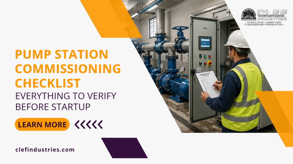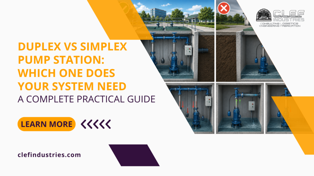

Choosing the right pump control panel is essential for reliable pump operation, equipment protection, and efficient system control. The panel serves as the central operating point of a pumping system, connecting the pumps and motors with starters, Variable Frequency Drives, sensors, alarms, and automatic controls.
A correctly designed panel allows pumps to start, stop, alternate, and respond to changing pressure, flow, or liquid levels. It can also protect motors and electrical equipment from overloads, phase problems, short circuits, dry-running conditions, and other operating faults.
However, pump control panels are not one-size-fits-all products. A panel suitable for a small irrigation pump may not provide the redundancy, automation, communication, or environmental protection required for a municipal or industrial pump station.
Selecting a panel based only on motor horsepower or initial price can result in poor performance, frequent faults, limited functionality, and expensive field modifications. The right selection should account for the complete application, including the number of pumps, motor data, control method, site conditions, sensors, alarms, operator needs, and plans for future expansion.
What Is a Pump Control Panel?
A pump control panel is an electrical enclosure containing the components required to operate, monitor, and protect one or more pumps. Depending on the system, it may include motor starters, circuit protection, overload relays, VFDs, programmable logic controllers, control relays, an HMI, communication equipment, and alarm devices.
The panel receives information from field instruments such as pressure transducers, float switches, level sensors, and flow meters. It uses these inputs to control the pumps according to a defined operating sequence.
For example, a pressure-controlled booster system may increase pump speed when discharge pressure drops. A wastewater or drainage system may start a pump when the liquid reaches a predetermined level. A duplex system may alternate between two pumps to balance operating hours and maintain standby capacity.
| Panel component | Main purpose |
|---|---|
| Main disconnect | Isolates incoming electrical power |
| Circuit protection | Protects wiring and equipment from electrical faults |
| Starter or VFD | Starts the motor and controls its operation |
| Overload protection | Protects the motor from sustained overcurrent |
| PLC or control relays | Manage the operating sequence |
| HMI | Displays status, alarms, readings, and controls |
| Sensors and switches | Provide pressure, flow, level, or status feedback |
| Alarm equipment | Alerts operators to abnormal conditions |
The correct panel should operate the system safely while remaining straightforward to inspect, troubleshoot, maintain, and upgrade.
Why Pump Control Panel Selection Matters
The control panel influences nearly every part of pump station performance. If it is undersized, poorly configured, or missing important control functions, the system may experience repeated cycling, unstable pressure, nuisance trips, excessive energy use, or premature equipment wear.
A properly selected pump control panel coordinates pump operation with actual system demand. It can alternate pumps to balance runtime, stage additional pumps during periods of higher demand, prevent dry running, and stop equipment when unsafe conditions are detected.
Panel design also affects serviceability. Clearly labelled devices, organized wiring, accessible components, accurate drawings, and useful fault information can help technicians identify problems more quickly.
CLEF Industries provides customized VFD and automation systems designed around specific pump-station requirements, including speed regulation, automatic control, and solutions intended to improve reliability and operating efficiency.
Define the Pumping Application First
The selection process should begin with a clear understanding of what the pumping system must accomplish. A panel for irrigation, wastewater, drainage, industrial processing, or municipal water service will not necessarily use the same control logic or components.
The fluid being pumped, required flow, operating pressure, normal demand, peak demand, suction conditions, and daily operating schedule all influence the panel design. The criticality of the system should also be considered. A noncritical transfer pump may tolerate temporary downtime, while a municipal or industrial station may require redundancy, remote alarms, and backup power integration.
A pressure-based system normally uses a pressure transducer to tell the controller when to increase or reduce pump output. A level-based system may use float switches or a continuous level transmitter. Irrigation systems may need to respond to scheduled zones and changing flow requirements.
Important details to establish at this stage include:
- The fluid and process being served
- Required flow and pressure
- Normal and peak operating demand
- Indoor or outdoor installation
- Required redundancy
- Remote monitoring and alarm needs
Defining the application first prevents the panel from being designed around incomplete assumptions.
Match the Panel to the Number of Pumps
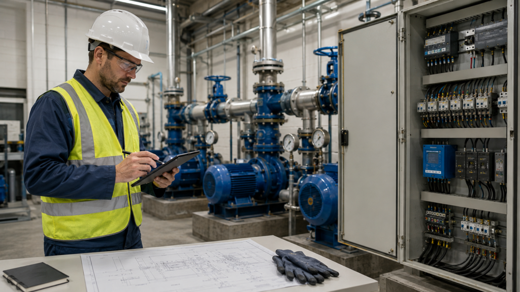
The number of pumps determines the panel size, motor-control components, and operating sequence. A simplex panel controls one pump, while duplex, triplex, and larger systems must coordinate multiple pumps.
A simplex system may be appropriate where one pump can meet demand and short periods of downtime are acceptable. A duplex arrangement provides additional flexibility because one pump can operate as the lead unit while the second functions as the lag or standby pump.
In a duplex system, the panel may alternate the lead pump after each cycle or according to accumulated runtime. If demand rises beyond the lead pump’s capacity, the lag pump can start automatically. If one pump fails, the panel may transfer the operating command to the available unit and activate an alarm.
| Pump arrangement | Typical control requirement |
|---|---|
| Simplex | Start and stop one pump |
| Duplex | Pump alternation, lead-lag operation, and standby capacity |
| Triplex | Staged operation and runtime balancing |
| Multi-pump | Advanced sequencing, communication, and demand management |
The operating sequence should explain how the system responds during normal demand, peak demand, equipment failure, sensor failure, and restoration of electrical power.
Confirm Motor and Electrical Requirements
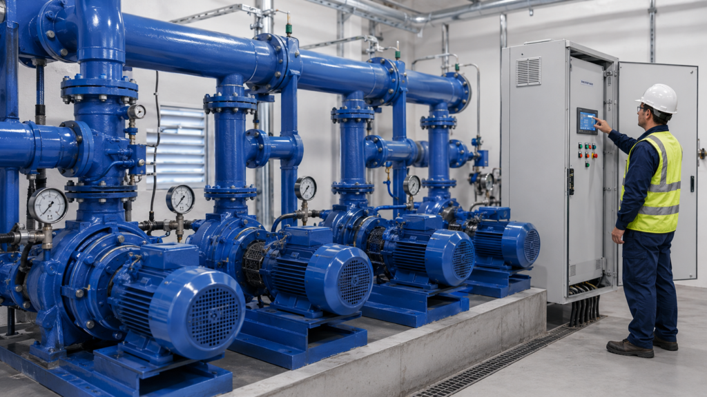
A pump control panel must match both the connected motors and the available electrical service. Motor horsepower is important, but it is not enough by itself to select the correct components.
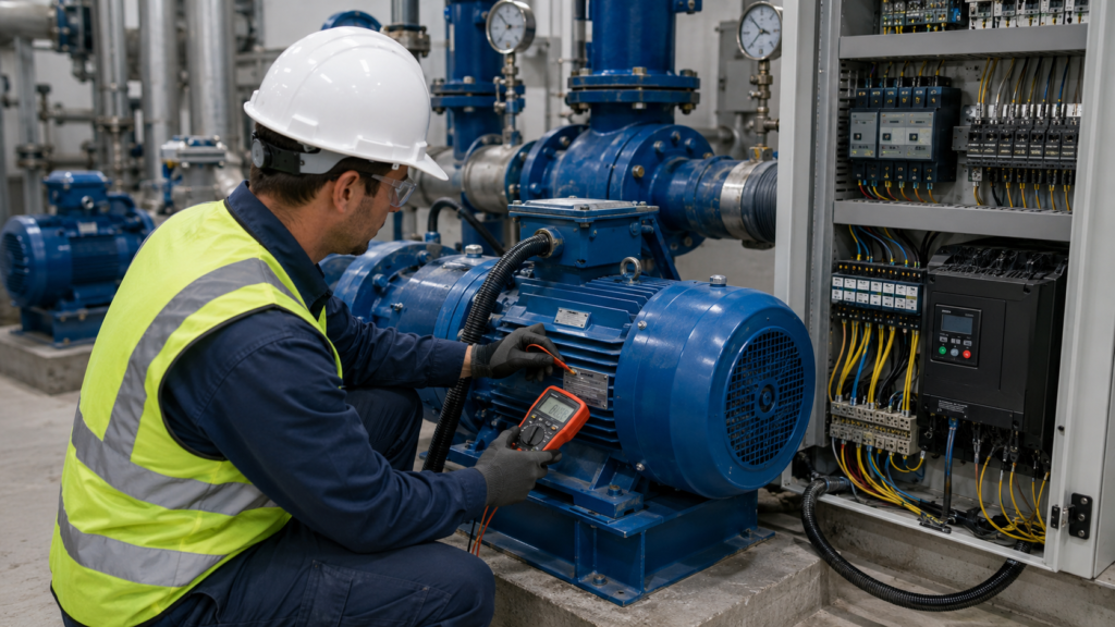
The panel designer should confirm voltage, phase, frequency, full-load amperage, service factor, starting current, insulation characteristics, and motor type. The available electrical service should also be reviewed for fault-current capacity, voltage stability, grounding, and disconnect requirements.
Starters, overload devices, breakers, fuses, conductors, and disconnects must be selected around the actual motor and system data. Incorrectly sized equipment may cause nuisance trips or fail to provide adequate protection during a fault.
For retrofit projects, existing wiring and electrical infrastructure should be inspected before assuming they can support a replacement panel, additional pump, or larger motor. CLEF’s engineering services cover mechanical, electrical, and control-system design, including equipment selection, drawings, specifications, and project documentation.
Choose the Appropriate Motor-Control Method
The panel may use an across-the-line starter, a soft starter, or a Variable Frequency Drive. The correct choice depends on the application, motor size, hydraulic conditions, and required level of control.
An across-the-line starter applies full voltage to the motor immediately. It is comparatively simple and may suit smaller, constant-demand systems, but it produces high starting current and greater mechanical stress.
A soft starter gradually increases voltage during startup. This reduces electrical inrush and provides smoother acceleration, although it does not normally regulate motor speed during regular operation.
A VFD controls motor frequency and speed. It is particularly valuable where pressure, flow, or demand changes throughout the operating cycle.
| Control method | Best suited for | Primary advantage |
|---|---|---|
| Across-the-line starter | Basic constant-demand systems | Simplicity |
| Soft starter | Systems needing smoother startup | Reduced starting stress |
| VFD | Variable-pressure or variable-flow systems | Speed and process control |
VFDs can help reduce pump cycling, maintain steadier pressure, and match pump output to changing demand. However, the design must account for motor compatibility, cooling, enclosure temperature, grounding, cable installation, and drive programming.
CLEF Industries offers customized VFD systems and automation solutions for pump stations, as well as troubleshooting and servicing support.

Select Sensors, Controls, and Alarms
A control panel can only respond correctly when it receives accurate information from the system. The required field instruments depend on whether the pumps are controlled by pressure, level, flow, time, or another process condition.
Pressure-controlled systems commonly use a pressure transducer to provide continuous feedback. Level-based stations may use float switches or a level transmitter. Flow meters, pressure switches, temperature sensors, and phase monitors may provide additional operating or protective inputs.
The alarm strategy should reflect the consequences of equipment failure. A small noncritical pump may only require local indication, while a remote or critical station may need an alarm beacon, audible horn, dialer, SCADA connection, or automatic notification.
Typical alarms may include pump failure, motor overload, VFD fault, high or low pressure, abnormal liquid level, sensor failure, phase loss, power failure, or communication loss.
Alarm messages should be specific enough to help an operator understand the condition. A generic fault light provides less value than a clear indication identifying the affected pump or device.
Consider the Installation Environment
The physical location of the panel has a major effect on reliability. Equipment installed inside a clean, conditioned room has different requirements from a panel exposed to rain, dust, sunlight, irrigation chemicals, condensation, high temperatures, or corrosive conditions.
The enclosure should provide protection suitable for the environment. Depending on the site, the panel may require sealed doors, corrosion-resistant materials, filters, heaters, ventilation fans, cooling equipment, sun shields, or additional flood protection.
The following conditions should be reviewed before selecting the enclosure:
- Ambient temperature and direct sunlight
- Moisture, condensation, and washdown exposure
- Dust, debris, and chemical contamination
- Flood risk and mounting height
- Ventilation and service clearance
Heat management is especially important when a panel contains VFDs and other electronics. CLEF’s existing VFD guidance identifies airflow, enclosure temperature, contamination, and cooling as important factors in preventing overheating and premature failure.
The enclosure should also provide sufficient space around components for safe access and airflow. Packing equipment too tightly may make maintenance difficult and increase internal temperature.
Plan for Automation and Future Expansion
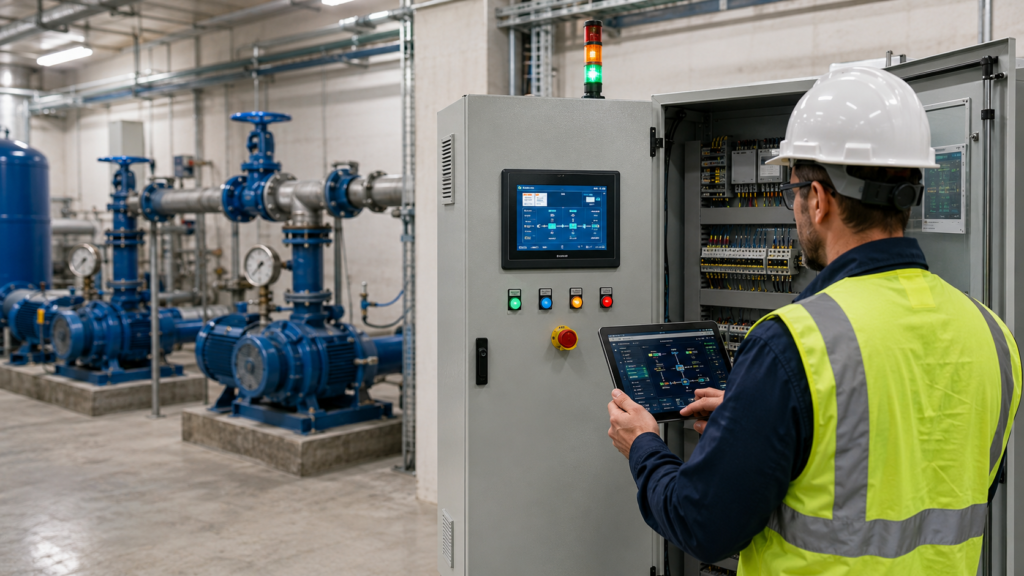
Many pump stations require more than local start and stop controls. Owners may need remote monitoring, operating trends, alarm history, automatic scheduling, runtime balancing, or communication with a larger facility system.
A PLC can manage advanced sequencing, fault responses, and communication. An HMI can display pressure, flow, pump status, motor current, VFD speed, alarms, and operating hours.
Before finalizing the panel, consider whether the system may later need another pump, additional sensors, remote access, backup-power integration, data logging, or expanded alarm outputs.
Providing spare enclosure space, terminal points, communication ports, and PLC input/output capacity can reduce the cost and disruption of future modifications
.
Standard Panel or Custom Pump Control Panel?
A standard panel may be suitable for a simple application with common motor sizes and basic control requirements. It can offer faster availability and lower initial engineering costs.
A custom pump control panel is often more appropriate when the application involves multiple pumps, VFDs, specialized instrumentation, remote communication, unusual site conditions, or a detailed sequence of operation.
| Standard panel | Custom panel |
|---|---|
| Suitable for basic applications | Designed around the exact application |
| Limited modification options | Flexible component and control selection |
| Often available faster | Supports complex sequencing and automation |
| May require field changes | Built around installed equipment and conditions |
CLEF Industries provides fabrication and design support for pump-station equipment and customized control solutions, allowing the panel to be developed around the project rather than forcing the project to fit a generic panel.
Common Selection Mistakes
Several avoidable mistakes can reduce reliability:
- Choosing a panel based only on horsepower
- Using the wrong enclosure for the environment
- Omitting important sensors or alarms
- Providing inadequate cooling for VFDs
- Failing to define the operating sequence
- Leaving no capacity for future expansion
These problems are easier and less expensive to correct during the design stage than after installation.
How CLEF Industries Can Help
Choosing the right pump control panel requires coordination between the pumps, motors, electrical service, sensors, control logic, environment, and operator requirements.
CLEF Industries supports pump-station projects through engineering, fabrication, customized VFD and automation systems, equipment upgrades, troubleshooting, repair, and new project design. Its service offering is built around pump, motor, control, and VFD requirements for new and retrofit applications.
A properly engineered panel can improve operating reliability, simplify maintenance, support more efficient pump control, and provide the information operators need to respond to faults.
Conclusion
The right pump control panel should do more than turn a motor on and off. It should protect the equipment, respond accurately to changing demand, communicate useful operating information, and support safe maintenance.
Begin by defining the pumping application, number of pumps, motor data, electrical service, required control method, sensors, alarms, environmental conditions, and future automation needs.
Taking the time to match the panel to the complete application can reduce downtime, prevent unnecessary equipment stress, and make future servicing and expansion easier.
For support with custom pump control panels, VFD systems, engineering, fabrication, or pump-station upgrades, contact CLEF Industries to discuss the requirements of your application.